Amazon Elastic Kubernetes Service, or Amazon EKS, runs the Kubernetes control plane for you, keeps it highly available and exposes the cluster API. The rest of the platform still depends on compute, networking, identity, DNS and storage working together.
An EKS cluster showing ACTIVE only confirms that the control plane exists. It does not prove that nodes have joined, Pods can obtain addresses, add-ons are healthy or your kubectl identity is authorised. This article separates those systems in a traditional EC2-backed EKS cluster using managed node groups, rather than EKS Auto Mode or Fargate.
Control Plane
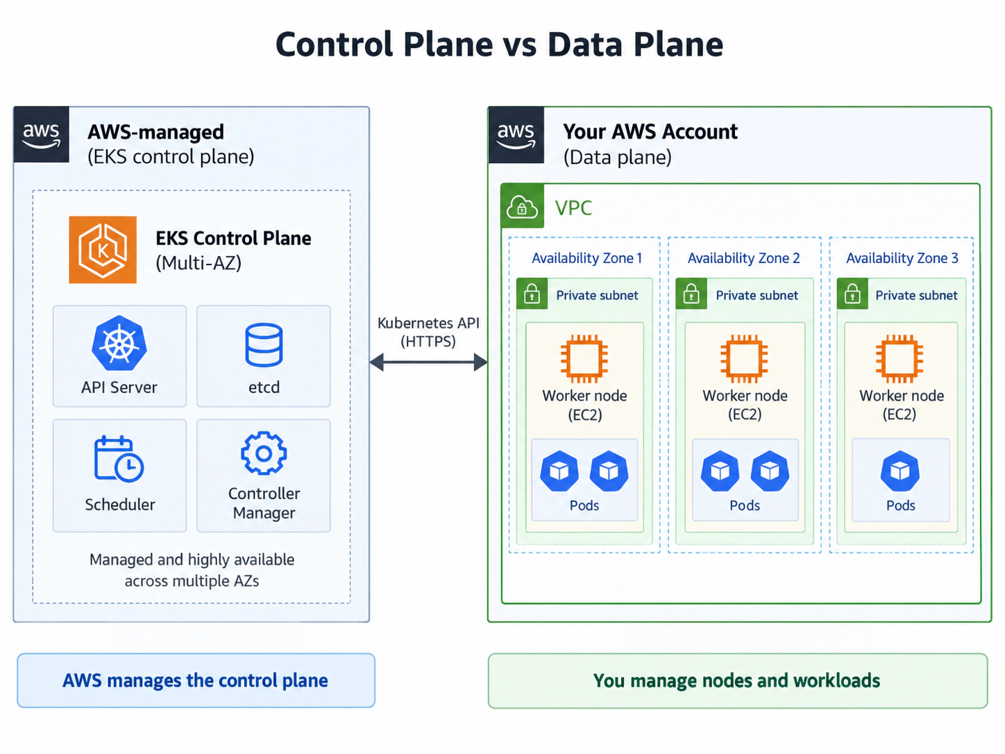
A Kubernetes cluster has a control plane, which records and reconciles desired state, and a data plane, where application workloads run. In EKS, AWS operates the API servers, etcd, scheduler and controllers across multiple Availability Zones; you do not receive or patch their underlying hosts.
These are the standard Kubernetes control-plane components, but AWS manages their availability and infrastructure.
The managed boundary stops there. AWS does not automatically provide healthy worker capacity, working Pod networking or application permissions merely because the API is available.
The API server
The Kubernetes API server is the cluster's main interface. Commands such as these send requests to it:
kubectl get pods

kubectl apply -f deployment.yaml
The API server authenticates and authorises the caller, validates the resource and runs admission controls before recording the desired state.
Schedulers, controllers and kubelets also communicate through this API rather than modifying cluster state directly. That makes the API server the consistent control point for both users and internal Kubernetes components.
You can retrieve the API endpoint for an EKS cluster using the AWS CLI:
aws eks describe-cluster \
  --name my-cluster \
  --query 'cluster.endpoint' \
  --output text
The returned address is Kubernetes' management endpoint, not an application endpoint.
etcd
etcd is the distributed key-value database holding Deployments, Pods, Services, Secrets, ConfigMaps and node registrations. Kubernetes stores declarations such as replicas: 3 as desired state; controllers then compare that state with reality.
AWS operates and protects etcd in EKS, including its underlying hosts, storage and replication.
Scheduler
The scheduler chooses a worker node for each Pod using available CPU and memory, selectors, affinity, topology constraints, taints and tolerations. It records placement; the node's kubelet starts the workload.
This distinction matters during troubleshooting: a Pending Pod may have failed placement even though every existing container runtime is healthy.
Controller manager
Controllers continuously reconcile desired and actual state. If a Deployment requests three replicas but only two exist, its controllers create a replacement Pod. This reconciliation is why Kubernetes recovers automatically from many workload failures.
Controllers do not normally repair a particular failed container. They restore the declared state, often by creating a new Pod and allowing the scheduler to place it again.
AWS manages these control-plane decisions; your data plane executes them.
Networking
Worker nodes live inside your VPC, while the control plane runs in AWS-managed infrastructure. EKS therefore needs secure network paths between both sides of the cluster.
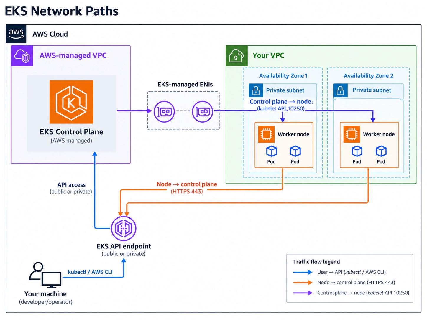
The subnet IDs supplied during cluster creation do not host the control-plane servers. EKS instead creates two to four requester-managed Elastic Network Interfaces (ENIs) in those subnets, giving the managed control plane private VPC connectivity and security-group associations.
The subnets must span at least two Availability Zones and each needs at least six available IP addresses; AWS recommends sixteen. Their finite address space is also consumed by nodes, Pods, load balancers and other networking components.
API endpoint access
The Kubernetes API endpoint can be configured for:
- Public access
- Private access
- Public and private access
Public access lets approved external networks reach the API, while private access keeps node and in-VPC traffic on the VPC path. A private-only endpoint requires administrators and automation to have network connectivity into the VPC.
You can inspect the current configuration using:
aws eks describe-cluster \
  --name my-cluster \
  --query 'cluster.resourcesVpcConfig.{
    Public:endpointPublicAccess,
    Private:endpointPrivateAccess,
    PublicCIDRs:publicAccessCidrs
  }'
A development cluster might enable both modes while limiting public access to known CIDRs. Authentication is still required, but allowing 0.0.0.0/0 unnecessarily exposes the API endpoint to the entire internet.
Node-to-control-plane communication
Each node's kubelet must reach the API endpoint over HTTPS during bootstrap and normal operation. If that path or authentication fails, a healthy EC2 instance may never register as a Kubernetes node.
That is why these two commands answer very different questions:
aws ec2 describe-instances

kubectl get nodes
The first tells you whether EC2 exists and is running. The second tells you whether Kubernetes has successfully registered and accepted the node.
This path depends on subnet routes, DNS resolution, security groups, endpoint configuration and the node IAM role. Testing only EC2 health therefore misses several requirements for cluster membership.
Control-plane-to-node communication
Traffic also flows back from the control plane to nodes. Operations such as kubectl exec and kubectl logs can involve the kubelet API on TCP 10250, so overly restrictive security-group rules can break Kubernetes even when ordinary application traffic works.
Useful investigation commands include:
kubectl get nodes -o wide

kubectl describe node <node-name>
For lower-level network inspection, you can also examine the cluster security groups:
aws eks describe-cluster \
  --name my-cluster \
  --query 'cluster.resourcesVpcConfig.clusterSecurityGroupId'
Kubernetes often reports the symptom first, while the cause is a route table, security group, subnet, DNS setting or endpoint configuration underneath it.
Worker Nodes
Application workloads need compute in the data plane. In an EC2-backed cluster, each worker node is an EC2 instance containing an operating system, Kubernetes networking, a kubelet and a container runtime such as containerd.
The kubelet registers the node, watches for assigned Pods, instructs the runtime to start containers and reports health to the API server.
During bootstrap, the instance needs the correct cluster name, API endpoint and certificate authority data, plus an IAM identity EKS accepts as a node. A mistake in user data, DNS, routing or permissions can leave the instance running but absent from Kubernetes.
You can see registered nodes using:
kubectl get nodes
Look for STATUS: Ready. EC2 running only means the virtual machine exists; Kubernetes Ready means the cluster can communicate with it and considers it able to accept workloads.
For more detail:
kubectl describe node ip-10-0-11-25.eu-west-2
This exposes capacity, conditions, taints, Pod addressing, resource allocation and recent events.
Managed node groups
EKS managed node groups provide an AWS-managed lifecycle around EC2 worker nodes. The instances still run in your AWS account and normally belong to an Auto Scaling Group, but EKS assists with operations such as provisioning, updates and draining nodes during replacement.
You still choose instance types, subnets, scaling limits and much of the operating-system configuration. Managed does not mean AWS decides the workload architecture for you.
List and inspect node groups with:
aws eks list-nodegroups \
  --cluster-name my-cluster

aws eks describe-nodegroup \
  --cluster-name my-cluster \
  --nodegroup-name system-nodes
The minimum, desired and maximum values control EC2 capacity. Kubernetes scheduling remains separate: adding instances supplies machines but does not decide Pod placement.
Why bootstrap nodes matter
Karpenter can provision EC2 capacity for unschedulable workloads, but Karpenter itself runs as a Pod. With zero nodes, it—and system workloads such as CoreDNS or storage controllers—has nowhere to start.
A common design is therefore:
Small managed node group
        |
        v
Core cluster services start
        |
        v
Karpenter starts
        |
        v
Application workloads appear
        |
        v
Karpenter provisions additional capacity
A small managed node group therefore acts as the fixed bootstrap layer while Karpenter supplies most application capacity.
IAM & RBAC
EKS joins two security systems: AWS IAM establishes the AWS identity, while Kubernetes RBAC determines what that identity can do inside the cluster.
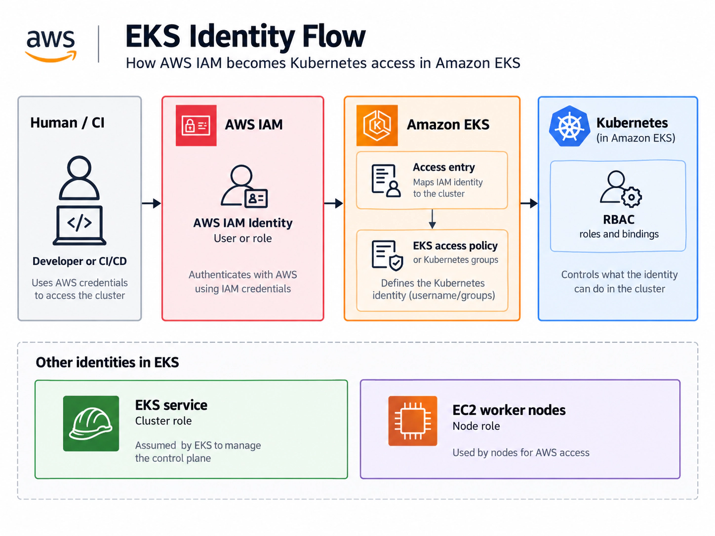
EKS maps the IAM principal into cluster access before Kubernetes authorisation evaluates the requested action.
These stages are separate: IAM authentication can succeed while Kubernetes returns Forbidden, because the authenticated principal lacks the required RBAC permission.
Checking your AWS identity
Before troubleshooting Kubernetes access, check which AWS identity your terminal is actually using:
aws sts get-caller-identity
With multiple AWS profiles, verify the intended profile explicitly:
AWS_PROFILE=nabil aws sts get-caller-identity
The wrong AWS identity causes Kubernetes authentication to fail even when kubeconfig is correct.
kubeconfig
To configure kubectl for an EKS cluster:
aws eks update-kubeconfig \
  --region eu-west-2 \
  --name my-cluster
This writes the API and certificate configuration to ~/.kube/config. Inspect the active and available contexts with:
kubectl config current-context
kubectl config get-contexts
For EKS authentication, the AWS CLI normally generates a short-lived token from your current AWS credentials.
Consequently, switching AWS profiles can change the identity presented to the same kubeconfig context without changing the cluster endpoint itself.
EKS access entries
Modern EKS clusters can use access entries to map IAM principals into cluster permissions.
List them with:
aws eks list-access-entries \
  --cluster-name my-cluster
You might see an identity such as arn:aws:iam::123456789012:role/platform-engineer.
An entry can use EKS access policies or map the principal to Kubernetes groups. For supported configurations, this is preferable to relying entirely on the older aws-auth ConfigMap.
The access entry answers who may enter the cluster; EKS access policies or RBAC answer which Kubernetes actions that principal may perform.
Kubernetes RBAC
Test Kubernetes permissions directly:
kubectl auth can-i get pods
kubectl auth can-i delete deployments -n production
The first may return yes and the second no. Broad AWS permissions do not automatically grant Kubernetes access, and cluster administration does not grant wider AWS permissions.
Cluster role, node role and workload identity
The cluster IAM role lets EKS perform required AWS operations, while the node IAM role supports node-level actions such as pulling from ECR. Applications should use EKS Pod Identity or IAM Roles for Service Accounts instead of inheriting broad node permissions. Keeping these identities separate limits the impact of a compromised workload.
Cluster Add-ons
A healthy API server and Ready nodes are not enough. Workloads also depend on components that provide Pod networking, DNS, Service routing and storage integration; EKS can manage several of them as add-ons.
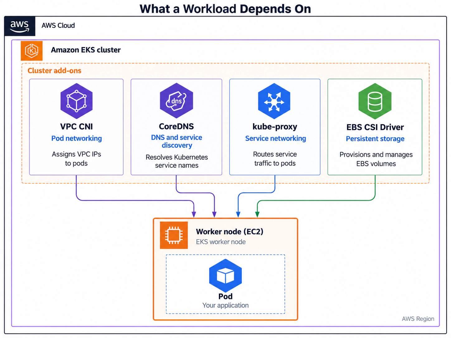
List add-ons and inspect their Kubernetes workloads with:
aws eks list-addons \
  --cluster-name my-cluster

kubectl get pods -n kube-system
Common results include vpc-cni, coredns, kube-proxy and aws-ebs-csi-driver.
Amazon VPC CNI
The Amazon VPC CNI configures container networking and normally assigns Pods addresses from the VPC rather than a separate overlay.
This allows Pods to participate directly in VPC routing and security designs, but it also ties Pod density to available subnet addresses and the networking limits of each EC2 instance type.
You can see Pod IP addresses using:
kubectl get pods -o wide
Because those addresses consume real VPC capacity, subnet IP exhaustion can stop new Pods even when nodes still have CPU and memory available.
Useful commands include:
kubectl get daemonset aws-node -n kube-system

kubectl logs -n kube-system \
  -l k8s-app=aws-node \
  --tail=100
Design subnet CIDR ranges for expected Pod density, not only EC2 instance count.
CoreDNS
Pods are ephemeral, so applications use stable Kubernetes Service names such as postgres.default.svc.cluster.local. CoreDNS resolves those names; if it fails, otherwise healthy applications cannot find databases, APIs or other internal services.
CoreDNS itself runs as Pods, so it needs schedulable worker capacity and working CNI networking before cluster DNS can become healthy.
Test DNS from a Pod and inspect CoreDNS with:
kubectl get deployment coredns -n kube-system

kubectl logs \
  -n kube-system \
  -l k8s-app=kube-dns

nslookup kubernetes.default.svc.cluster.local
kube-proxy
kube-proxy implements Service networking on each node. Clients use a stable Service address while kube-proxy programs rules that direct traffic to the selected Pods.
A Service with the correct ClusterIP can still fail if its selector matches no ready Pods, because Kubernetes then has no backend endpoints to program.
Inspect Services and their backends with:
kubectl get services
kubectl get endpoints
kubectl get endpointslices
If a Service exists but has no healthy backend endpoints, requests have nowhere to go.
EBS CSI Driver
Stateful workloads often need storage that survives container recreation. The EBS CSI Driver implements the Container Storage Interface between Kubernetes claims and Amazon EBS volumes.
Inspect storage resources and a failing claim with:
kubectl get pvc

kubectl get pv
kubectl describe pvc <pvc-name>
A claim stuck in Pending can indicate a StorageClass, CSI, IAM, capacity or Availability Zone problem. Because an EBS volume belongs to one AZ, Kubernetes must schedule its Pod where the volume can attach.
The controller component makes AWS API calls to provision or attach storage, while a node component performs the mount. Both the relevant IAM permissions and the Kubernetes components must be healthy.
From kubectl to Pod
The easiest way to understand how all of these systems interact is to follow a deployment from the developer's terminal to a running application.
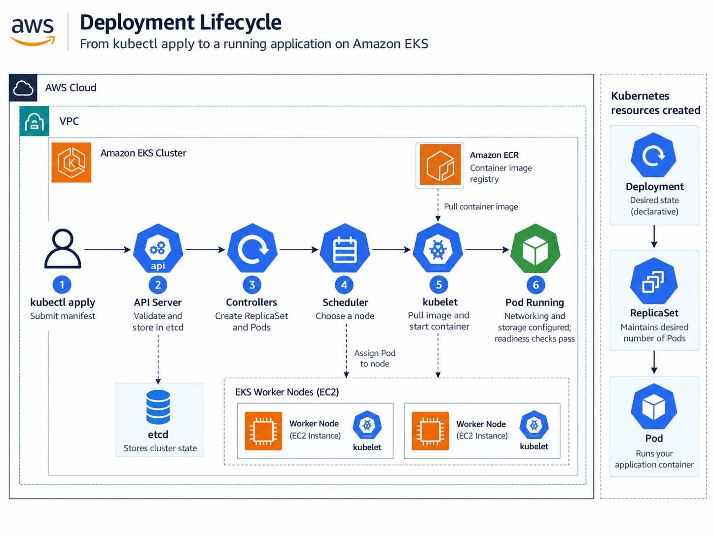
Consider this Deployment:
apiVersion: apps/v1
kind: Deployment
metadata:
  name: web
spec:
  replicas: 2
  selector:
    matchLabels:
      app: web
  template:
    metadata:
      labels:
        app: web
    spec:
      containers:
        - name: web
          image: nginx:latest
          ports:
            - containerPort: 80
You submit it using:
kubectl apply -f deployment.yaml
kubectl does not SSH into a node and start NGINX. It declares the desired state and several components act on it.
Step 1: kubectl reads the cluster configuration
kubectl reads kubeconfig to find the API endpoint, then uses your AWS identity to obtain EKS authentication.
Step 2: The API server receives the manifest
The API server authenticates and authorises the request, validates the manifest and stores the Deployment as desired state. Inspect the accepted resource with:
kubectl get deployment web
Acceptance does not mean the application is running yet.
The remaining work is asynchronous: controllers and nodes watch for the new state and react independently.
Step 3: Controllers create lower-level resources
The Deployment controller creates a ReplicaSet, which maintains the requested Pods: Deployment → ReplicaSet → Pods. Deleting one managed Pod does not remove the application because the ReplicaSet creates a replacement.
This separation lets a Deployment manage rollout strategy while the ReplicaSet concentrates on maintaining the required replica count.
Step 4: The scheduler chooses nodes
The scheduler evaluates capacity and constraints before assigning each new Pod to a node.
Common reasons a Pod cannot be scheduled include:
- Insufficient CPU or memory
- Node taints or affinity rules
- Topology constraints
- No suitable persistent-volume location
If no node qualifies, the Pod remains Pending. Inspect the Pod and recent events with:
kubectl describe pod <pod-name>

kubectl get events \
  --sort-by=.lastTimestamp
The events usually identify whether the blocker is capacity, a taint, an affinity rule or storage topology.
Step 5: kubelet receives the assignment
The selected node's kubelet asks the container runtime to create the containers. Images in ECR require working permissions and connectivity; wrong names, tags or credentials commonly produce ErrImagePull followed by ImagePullBackOff.
After pulling the image, the runtime creates the Pod sandbox and containers according to the specification. The kubelet continually reports their status back through the API.
Step 6: Pod networking is configured
The Amazon VPC CNI assigns the Pod an address and configures its network path.
The Pod cannot communicate normally until that setup succeeds, even if the image has already been downloaded to the node.
Watch this process using:
kubectl get pods -o wide -w
A Pod can move from ContainerCreating with no address to Running with a VPC IP once networking succeeds.
Step 7: Storage is attached if required
If the Pod uses an EBS-backed PersistentVolumeClaim, Kubernetes and the CSI driver create or locate the volume, attach it to the selected node and mount it. Failure can leave a valid image stuck in ContainerCreating.
Volume topology can also influence scheduling because the selected node must be in an Availability Zone compatible with the EBS volume.
Step 8: Health checks determine readiness
A running container is not automatically ready for traffic. Liveness probes decide when to restart it, readiness probes control whether it receives traffic, and startup probes protect slow initialisation.
Example:
readinessProbe:
  httpGet:
    path: /health
    port: 80
  initialDelaySeconds: 5
  periodSeconds: 10
If the readiness probe fails, the Pod may be Running while still showing READY 0/1.
The process exists, but Kubernetes does not yet consider it a healthy backend.
Services normally remove unready Pods from their usable endpoints, preventing traffic from reaching an application before it can respond safely.
Step 9: Services expose the workload
If you create a Service:
apiVersion: v1
kind: Service
metadata:
  name: web
spec:
  selector:
    app: web
  ports:
    - port: 80
      targetPort: 80
The Service selects Pods matching app=web. Inspect both sides with:
kubectl get pods -l app=web
kubectl get service web
Traffic can then travel from a load balancer to the Service, selected Pod and container—a path requiring AWS and Kubernetes networking to cooperate.
For internet-facing applications, an Ingress controller or AWS Load Balancer Controller can create the AWS load balancer and connect it to the Kubernetes routing model.
Pitfalls
EKS sits between AWS infrastructure and Kubernetes, so the visible symptom may be several layers away from its cause.
ACTIVE does not mean the cluster is ready
ACTIVE confirms only the control plane. Operational readiness still requires Ready nodes, healthy system add-ons, scheduled workloads and successful application health checks.
EC2 running does not mean Kubernetes node ready
An EC2 instance can be running while kubectl get nodes shows nothing. That points toward the bootstrap path, identity or connectivity rather than EC2 availability.
Check identity and the managed node group:
aws sts get-caller-identity

aws eks describe-nodegroup \
  --cluster-name my-cluster \
  --nodegroup-name <nodegroup-name>
Then inspect node-group or Auto Scaling events. Common causes include:
- The node IAM role
- Security groups or route tables
- DNS or API endpoint access
- Bootstrap configuration, including an incorrect cluster name or broken user data
IAM access does not equal Kubernetes access
An AWS administrator may still receive Error from server (Forbidden). Test the AWS identity, its EKS mapping and Kubernetes authorisation separately:
aws sts get-caller-identity

aws eks list-access-entries \
  --cluster-name my-cluster

kubectl auth can-i get pods
Subnet exhaustion can look like a scheduling problem
VPC addresses are cluster capacity. A node can have spare compute while new Pods fail because the subnet has no usable addresses.
Check Pod events and CNI health:
kubectl describe pod <pod-name>

kubectl get pods \
  -n kube-system \
  -l k8s-app=aws-node
Plan for nodes, Pods per node, load balancers, EKS ENIs, other resources and future growth—not only current EC2 instances.
Deployment order matters
Terraform dependencies should follow the real order: control plane, bootstrap nodes, core add-ons, Karpenter capacity and then applications. Creating everything concurrently can expose the bootstrap problem described earlier.
Pending means something different from CrashLoopBackOff
Pod status quickly narrows the investigation:
Pending: scheduling, capacity, volumes, selectors, taints or networking setup.ImagePullBackOff: image name, registry, ECR permissions or network access.CrashLoopBackOff: the container starts and repeatedly exits.ContainerCreating: Kubernetes is still preparing networking, volumes, runtime or configuration.
Check the current logs and, for a repeatedly restarting container, the previous instance:
kubectl logs <pod-name>

kubectl logs <pod-name> --previous
A practical troubleshooting sequence
Investigate from infrastructure upward: control plane, nodes, system components, workload and application output.
aws eks describe-cluster \
  --name my-cluster \
  --query 'cluster.status'

kubectl get nodes
kubectl get pods -n kube-system
kubectl get pods -o wide
kubectl describe pod <pod-name>
kubectl get events \
  --sort-by=.lastTimestamp
kubectl logs <pod-name>

# If necessary, verify Kubernetes permissions and AWS identity
kubectl auth can-i get pods
aws sts get-caller-identity
Each layer depends on the one beneath it, so a lower-level failure can create misleading symptoms above it.
Conclusion
Amazon EKS removes the work of operating Kubernetes' control plane, but nodes, network paths, IAM mappings, Pod addresses, DNS, Service routing and storage must still function together before an application is usable.
Once those responsibilities are separated, failures become easier to locate: scheduling, node bootstrap, identity, subnet capacity, image pulls, DNS, storage or the application itself. That understanding turns EKS from a black box into a platform you can design and troubleshoot deliberately.
The practical habit is to work upward from the control plane and network, through nodes and add-ons, to the workload and its traffic path. Each check removes an entire class of possible causes.